The detection function
First, an acoustic signal needs to be generated for the insonification of the medium. Then the echoes reflected by the tissues encountered throughout the studied area need to be recorded. Two subfunctions, one for emission and one for reception, need to be created. Emission and reception are both realized with the transducer (see acoustic section). A sweeping subfunction is responsible for controlling the motor to scan the medium and direct the transducer in the desired directions (see mechanical section). The commands of these subfunctions are described in the electronic section.
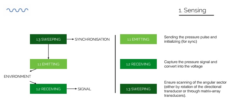
Figure 6: Functional analysis of the detection part
Acoustic part
Transducer
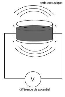
Figure 7: Piezoelectric effect
An ultrasound transducer converts an electric signal into an ultrasound signal and vice versa. It is enabled by a piezoelectric element, which can expand and contract in response to a potential difference. The medium surrounding the piezoelectric element is affected by this deformation and a wave is created (like when a stone is dropped into water). Therefore, an acoustic wave can be created (in the ultrasonic range, several MHz) from a potential difference (emission part). Conversely, when the piezoelectric element is deformed (eg. when an acoustic wave propagate through it) a potential difference can be measured between its two faces. The medium deformation is converted into an electric signal: the piezoelectric element can be used as a sensor (reception part).
The piezoelectric element can be considered as a 3-port network, with two mechanical ports (being the front and the back of the element) and one electrical port (being the electronic connection to the system) [11], [12].
The choice of the piezoelectric element is important as it sets the frequency of the emitted ultrasonic wave. It corresponds to the maximum gain in the emission/reception spectrum of the transducer (given by the manufacturer), and it depends on the geometry of the element. The working frequency influences penetration depth of the wave: the higher the frequency, the higher the attenuation of the wave for a given propagation distance.
| Ultrasound frequency (MHz) | Maximum examination depth (cm) |
|---|---|
| 2,5 - 3,5 | >15 |
| 5 | 10 |
| 7,5 | 5-6 |
| 10-12 | 2-3 |
Table 4: Maximum ultrasound examination depth for different frequencies [2].
When it is not emitting a signal, the transducer is used in listening mode. The emitted wave is reflected, refracted, scattered and absorbed by tissues, and part of the emitted signal is sent back towards the probe. It causes vibration of the transducer which converts the mechanical signal into an electrical signal
The piezoelectric element is excited by an analog pulse and vibrates on both its sides. The wave of interest is the one which propagates inside the medium of interest. Therefore the wave propagating in the other direction needs to be attenuated, as it can mask the signal of interest if it is reflected inside the probe back to the piezoelectric element. This attenuation is achieved using a backing medium.
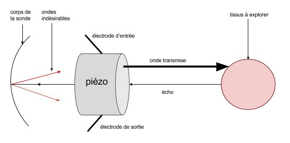
Figure 8: Ultrasound waves are emitted on both sides of the piezoelectric element
There is an impedance mismatch between the piezoelectric element and the examination medium. To minimise energy losses due to reflection at the interface, an impedance matching layer is placed on the piezoelectric element surface.
Finally, the focusing of the wave beam needs to be ensured. For common devices, composed of an array of transducers, focusing is achieved by wave interferences [13]. However, if there is only one emitting source (as is the case for the echOpen probe), interferences cannot be obtained. The focusing is achieved because of the shape of the output. A concave shape allows a focusing of the beam. The focusing distance depends on the characteristic frequency of the piezoelectric element, which is linked to the penetration depth. The focusing distance is given by a concave shape of the piezoelectric element itself, the impedance matching layer or a lens.
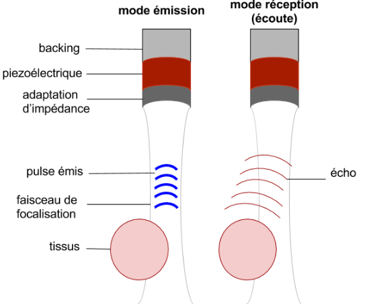
Figure 9: Pulse echo method [14], [15]
Piezoelectric material selection
The main component in the transducer is the piezoelectric element. Many different active materials can be used to build a transducer; they all have their pros and cons. Different categories of piezoelectric materials are piezoceramics[16], [17], piezoelectric polymers [18], [19] and single crystals [20]. Piezoelectric polymers such as polyvinylidene fluoride (PVDF) and copolymers (DFTrFE) have low acoustic impedance (~ 4 MRayl) which is ideal for impedance matching between the transducer and human tissue (~ 1.5 MRayl)[21]
As each piezoelectric material has a specific resonant frequency which sets the penetration depth, several transducers can be placed in the probe to get a range of penetrating depth.

| Piezoelectric material | Polymers | Single crystals | Piezoceramics |
|---|---|---|---|
| Pros | Low acoustic impedance (~4 MRayl). Ideal for impedance matching between the transducer and tissues (~1.5 MRayl). Low dielectric constant ideal for electric impedance matching | Fair electromechanical coupling Better contrast of the image Low dielectric constant ideal for sensitive single element transducers with large aperture | High electromechanical coupling |
| Cons | Low coupling coefficients | High acoustic impedance | High acoustic impedance |
High dielectric constant |
Table 5: Properties of piezoelectric materials
Backing selection
The backing attenuates the acoustic waves propagating from the back of the piezoelectric as much as possible. In order to achieve this a medium with high inhomogeneity can be used. Results from Desilet et al. [22] and experiments conducted by echOpen show that a material with low acoustic impedance (3 to 5 MRayl) is better to improve the pulse shape.
Matching impedance selection
It is used to minimise the reflection of the acoustic wave at the interface transducer/insonated medium. For a pulsed regime and a single adaptation layer, the impedance of the matching medium needs to verify:

The matching layer is generally a quarter wave plate: the thickness is equal to a quarter of the characteristic wavelength of the piezoelectric element in the insonated medium.
Mechanical part
Scanning probe
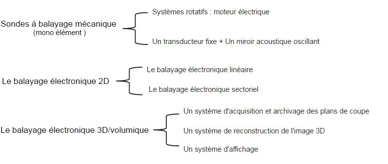
When the ultrasonic wave is emitted in a single direction (one transducer and one pulse), the ultrasound scanner can only record one line of the frame. In order to get a full frame, a scan of the studied area is needed. While in the past the doctor needed to do it manually, nowadays probes realise it automatically. The automatisation of the scanning process is the reason why people often talk about “dynamic” ultrasound imaging.
Motor
The motor enables scanning the area to explore. The motor type has to be adapted to the chosen scanning method [23]. The transducer is fixed on the motor’s head or on a movement converter part. It is important to realise that the oscillating scan by the motor implies accelerations and decelerations which can lead to noise in the signal. However the motor’s rotation can be modified into a pendulum motion.
The speed, angle and angular accuracy of the motor must be controlled. A DC motor can be used provided that you have a good encoder to continuously and accurately track its position. The synchronous stepper motor is less restrictive in terms of control and allows a better angular accuracy, as micro-steps can be used.
scanning speed: constant, 7.5 rotation/sec motion: clockwise and anticlockwise (oscillations) accuracy: from 30 to 1060 step over 60°
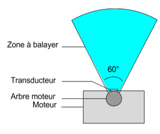
Figure 10: Example of specifications
Realisation of the electronic section
Power supplies
General power supply
For testing, it is advised to use a DC power supply rather than a battery. It allows for current control and avoid damaging components. However, once the probe is functional, a battery is better to reduce the noise.
Supply circuit
As each components do not require the same voltage, a converter is needed to divide the 18V input voltage.
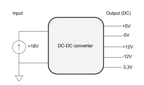
Figure 11: Desired function, example of values
Motor control
The motor is driven via a microcontroller, which is also used in other subfunctions for synchronisation purpose. For example, the pulse emission and the motor control can be synchronized. Care must be taken with use of the current supply in order to avoid frying the motor!
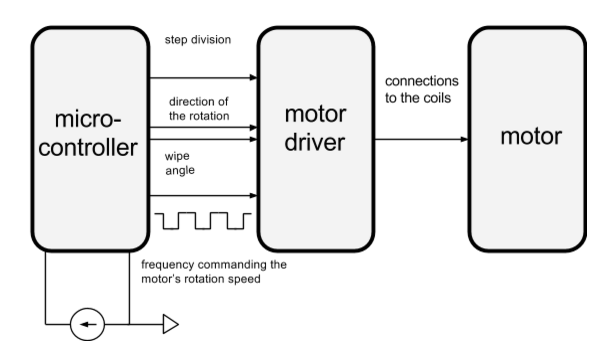
Figure 12: Motor control
Pulse command
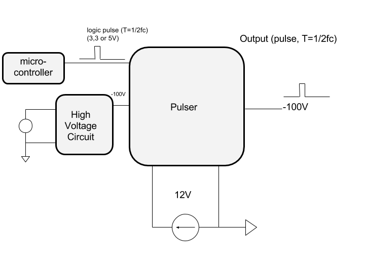
Figure 13: Pulse emission
High voltage circuit
To provide the excitation pulse to the piezoelectric element, a voltage of -100V is required as the transducer characteristic function is low. [24]
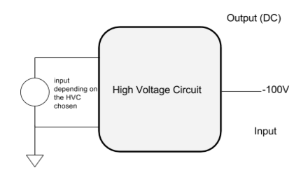
Figure 14: High voltage generation
Pulser
Using a logical pulse command (typically half the duration of the acoustic period) and a continuous supply of -100V, a -100V pulse of same duration is generated. A pulser is needed as command circuits cannot create a logical pulse at such high voltage.
Figure 15: Pulser
Pulser command
The pulse duration must be equal to half of the characteristic time of the transducer to get the best conversion rate (the expected response is an ultrasonic pulse). The repetition rate of the pulse is chosen depending on the motor’s speed and the desired accuracy. For a stepper motor, we can choose to emit one pulse every X steps. The pulse command must be coupled to the motor command. It is controlled by the microcontroller.
Reception mode
First filtering
Transducer response to an electrical pulse: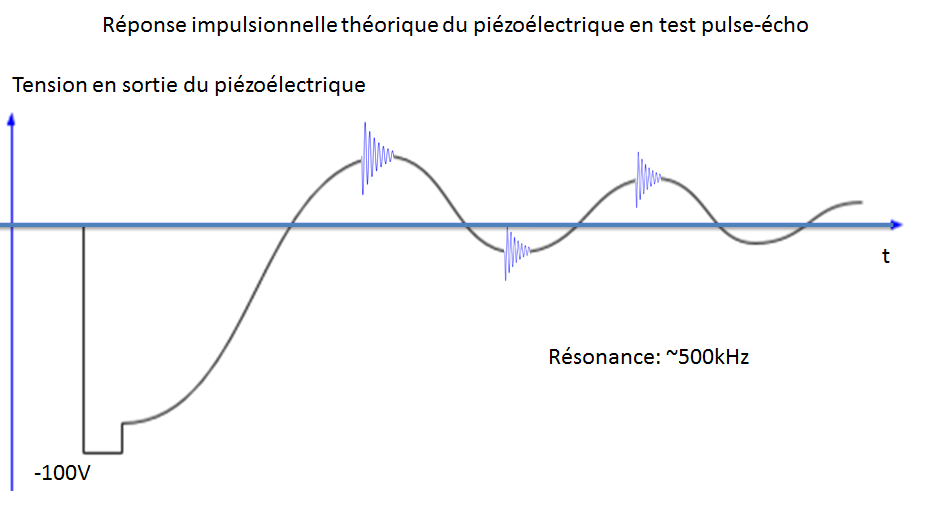 Figure 16: Raw output signal across the transducer
Analysis: a low frequency signal (nearly 500 kHz) appears across the transducer with high amplitude when it is excited by a pulse. This signal is not of interest and have a higher amplitude than the measured echo so we filter it with a high pass filter.
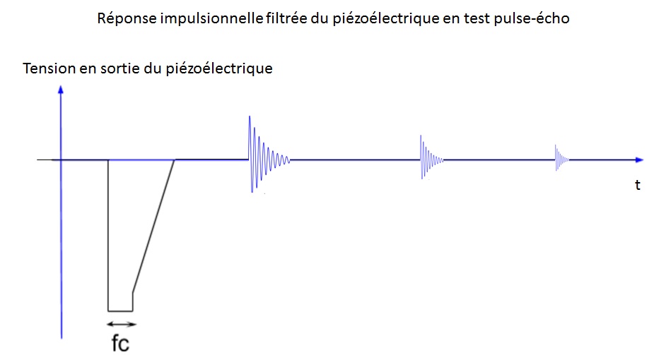
Figure 17: Filtered output signal across the transducer
Only the echo reflected by tissues is needed to be analyzed. The remaining part of the signal is considered as noise. The data acquisition is managed by a microprocessor. One can synchronize the beginning of acquisition with the pulse emission, and limit the duration of reception dt with respect to the penetration depth of the wave in tissues (related to the frequency fc), considering an average propagation speed of acoustic waves in tissues equal to the speed of an acoustic wave in water. The next circuits needs to be protected from the electric response of the transducer to the pulse (this response is of the order of 100V and high frequencies are not filtered by the high-pass filter). To do so, a T/R switch is used.
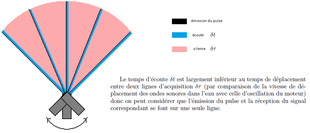
Figure 18: Scanned angle